Striving for simplicity in a complex world
The web portfolio of Arnout Groen,
a junior engineer driven by constant improvement

My projects:

Autonomous delivery drone
High end speakers
fully parametric cd wall display
ASCII
2048 game

See more about me
Products I’m familiar with


High end Speakers
July 2024
My favourite music,
made better
In the summer of 2024, I set out to build my own high-fidelity speaker system both to challenge my engineering skills and to experience my favorite music with studio-quality sound. What started as a personal passion project quickly became a hands-on application of acoustic engineering, cabinet design, and precision manufacturing
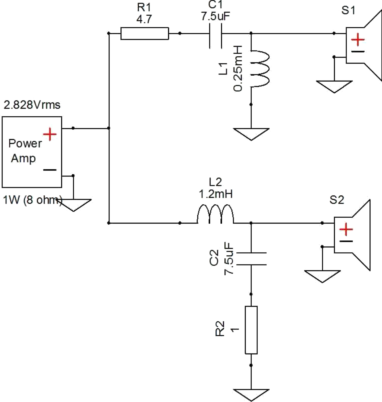
Crossover Design
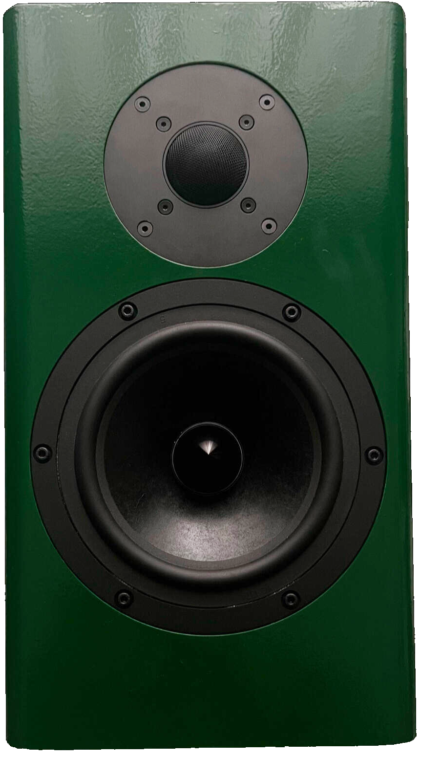
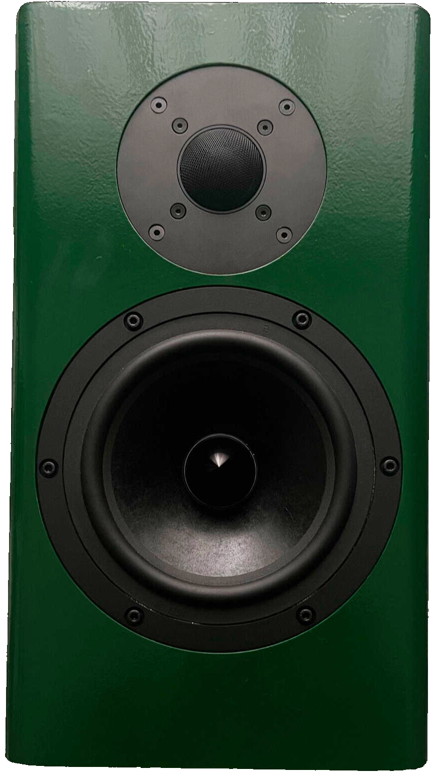
The design started with the heart of the system: the crossover. I chose a 2-way configuration, balancing a woofer (optimized for 35-8000 Hz) with a tweeter (handling everything from 1400-20000 Hz). Using XSim, I fine-tuned a passive crossover circuit to split the signal cleanly and flatten a +2.8 dB peak near 1000 Hz caused by the woofer’s natural response. The resulting frequency curve landed within ±3.5 dB across the full range delivering neutral, well-balanced playback.
(based on Samba MT crossover design)
Cabinet Design
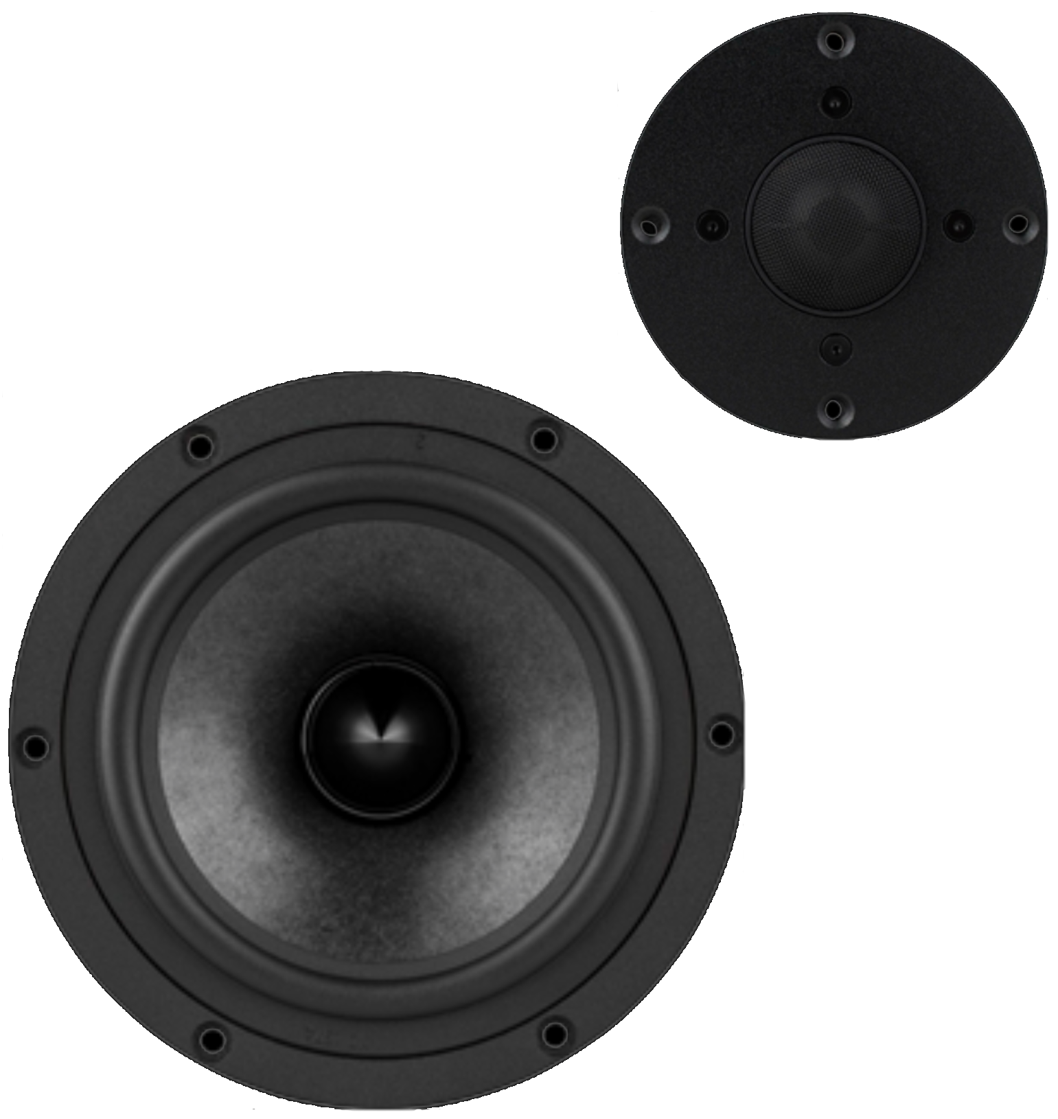
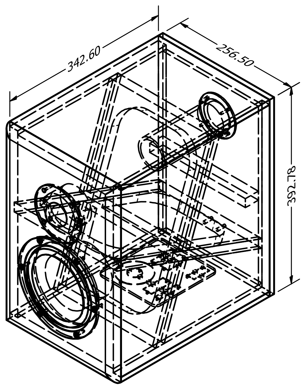
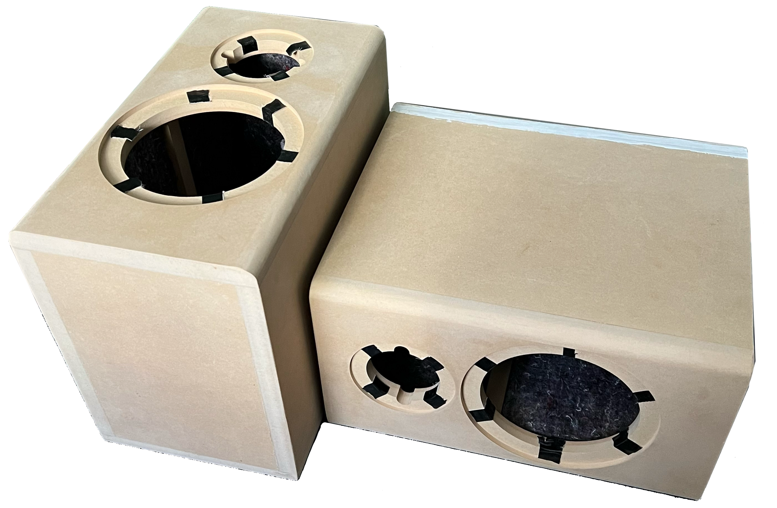
The cabinet is designed to keep the eigenfrequencies as low as possible in order to minimize interference with the speakers performance. This was achieved by increasing the stiffness of the cabinet.The angled braces on the inside of the speaker help with increasing the stiffness. Another side effect is that it scatters the sound waves around, which distributes the vibrations over a wide range of frequencies which in turn reduces any overpowering frequency peaks.The speaker baffle includes space for a woofer (low to mid frequency driver) and a tweeter (high frequency driver) which are located above each other. The baffle also includes rounded edges which reduces wave diffraction.
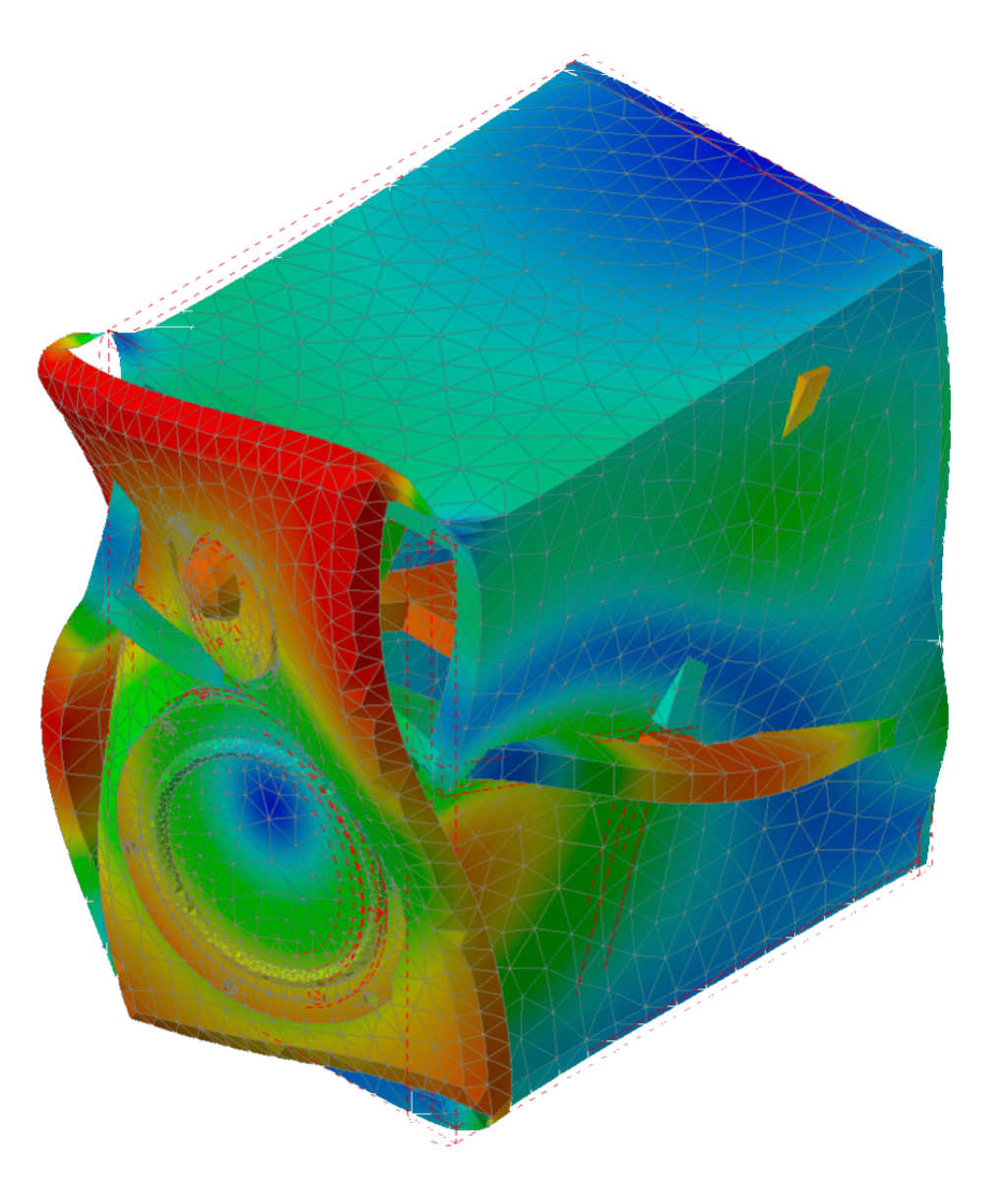
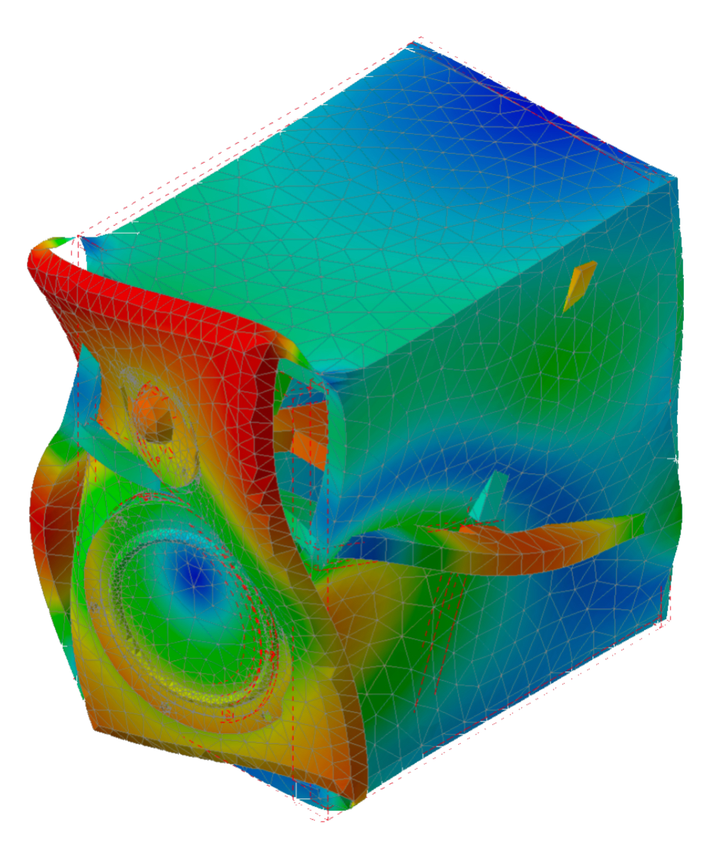
Cabinet Test
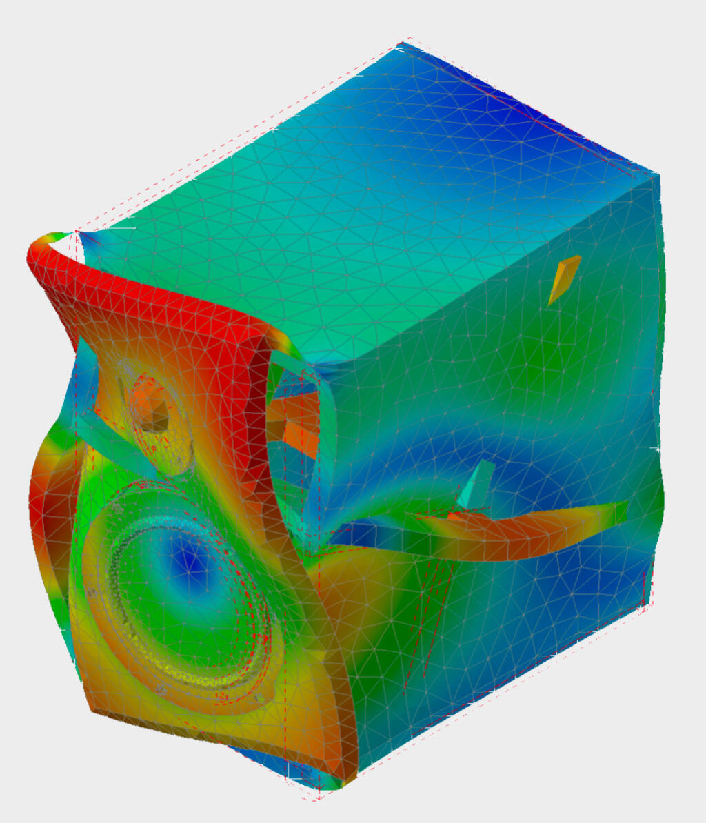
Once the acoustic side was defined, I shifted to mechanical performance. The cabinet cut from 19 mm MDF wasn’t just a box, but an active part of the system. Using FEM modal analysis in Inventor Nastran, I simulated resonance modes and iterated the design to shift the first mode down to 179 Hz, well below any crossover activity. Internal angled braces increased stiffness by an estimated 40%, while also scattering internal reflections to prevent frequency buildup. Rounded edges along the baffle minimized diffraction and helped maintain a clean sound stage.
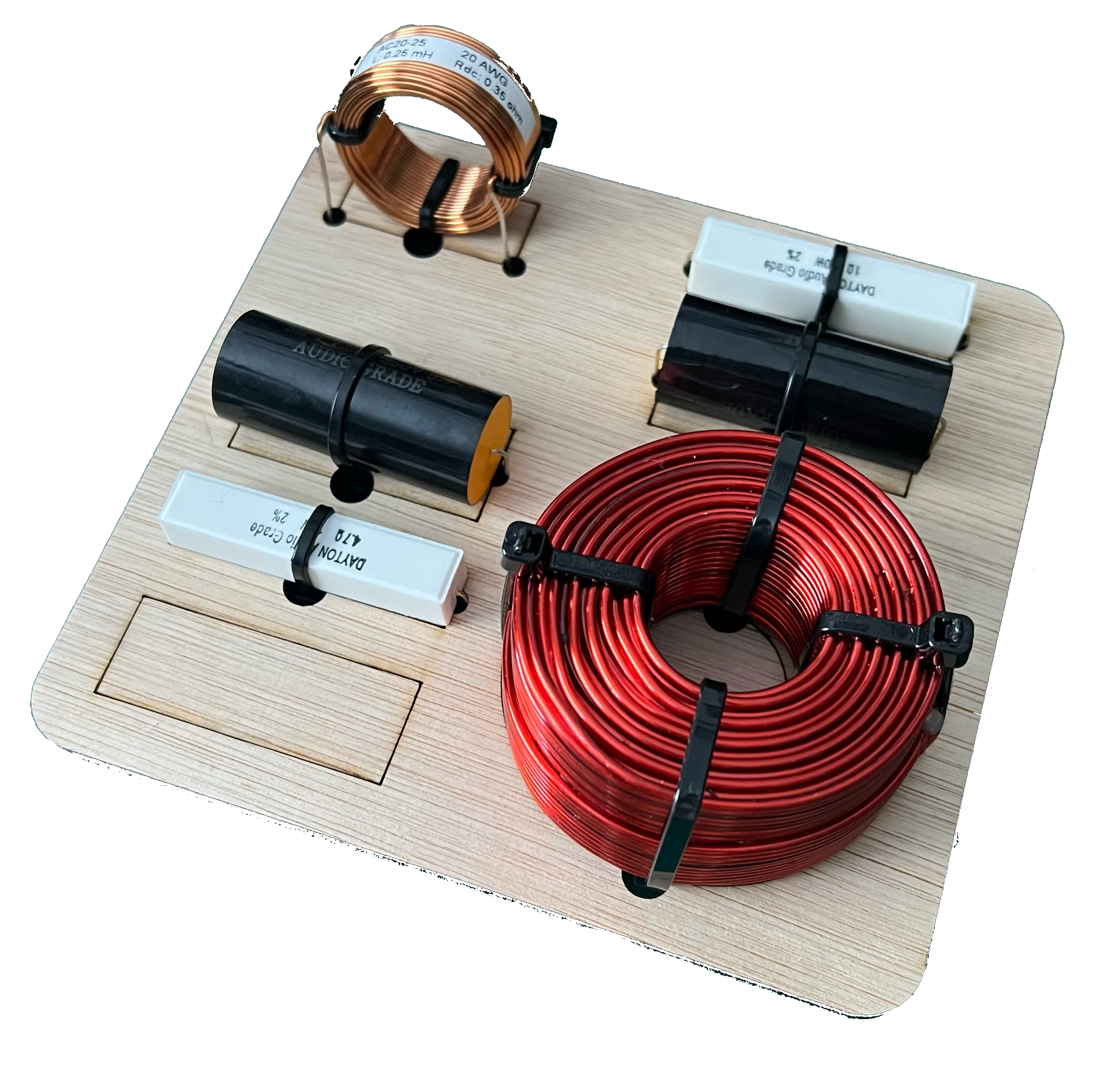
Crossover Fabrication
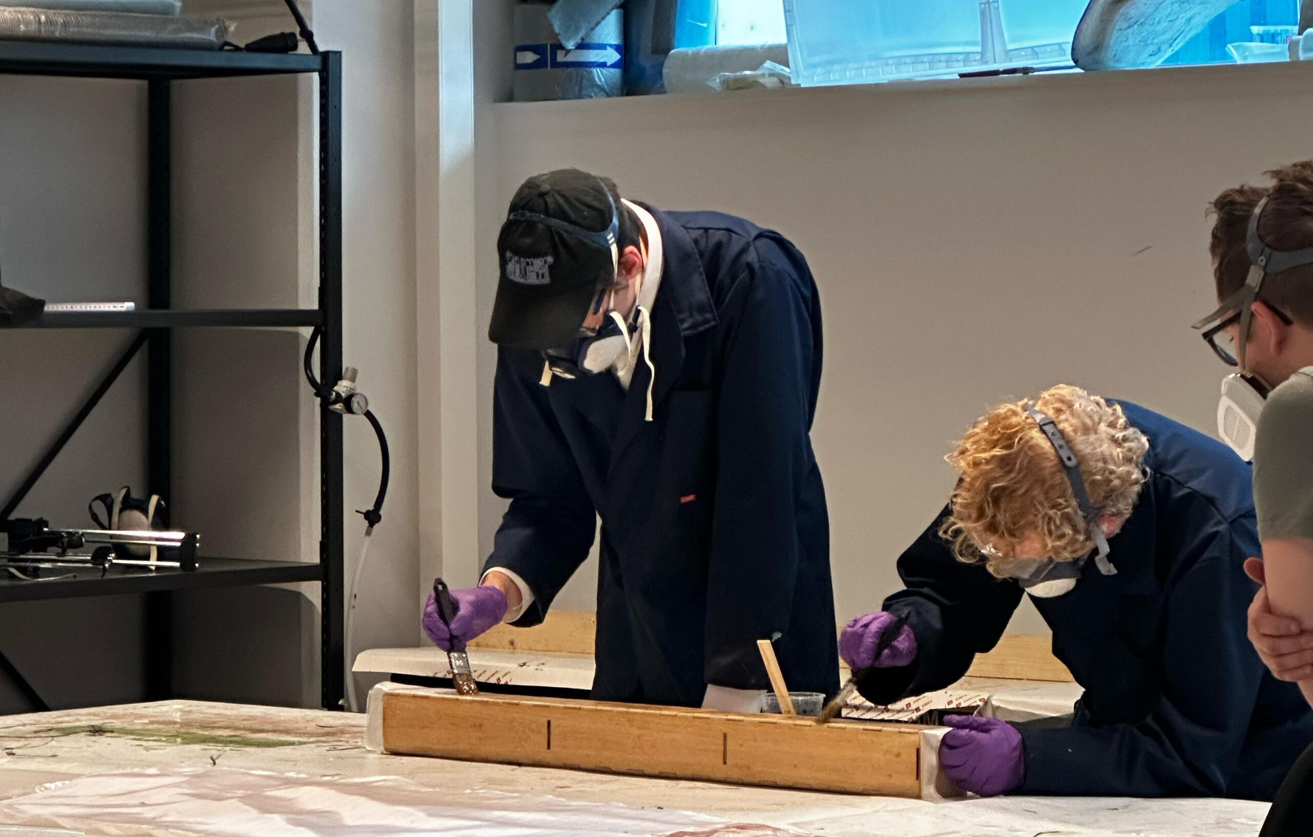
The crossover circuit itself was laser-cut into multiplex plywood for rigidity, and laid out to minimize electromagnetic interference: inductors were spaced apart and rotated 90° relative to each other. Wires were routed through the board and cleanly soldered on the reverse, resulting in a compact and serviceable layout.
Cabinet construction
For the cabinet production, I generated G-code in Fusion 360 CAM and partnered with a local CNC manufacturer to fabricate all panels achieving a full turnaround in under 8 hours. The final build was glued, clamped, and internally damped, with tests confirming airtight seals and consistent stiffness. I finished the enclosures with matte white primer and a deep green satin paint, designed to both blend into a modern interior and avoid unwanted acoustic reflections.
Final result
The finished speakers perform well beyond their cost: delivering clean lows, airy highs, and minimal distortion comparable to commercial models in the €400-500 class at around 50% of the cost. Just as importantly, they reflect my end-to-end process thinking, from acoustic modeling and material optimization to production strategy and finish quality.
Tools used in this project:


Skills applied in this project:
FEM analysis
Design for Manufacturing (DFM)
Design for Assembly (DFA)
Tolerance analysis
Rapid prototyping
Parametric design
Acoustic design
Circuit layout
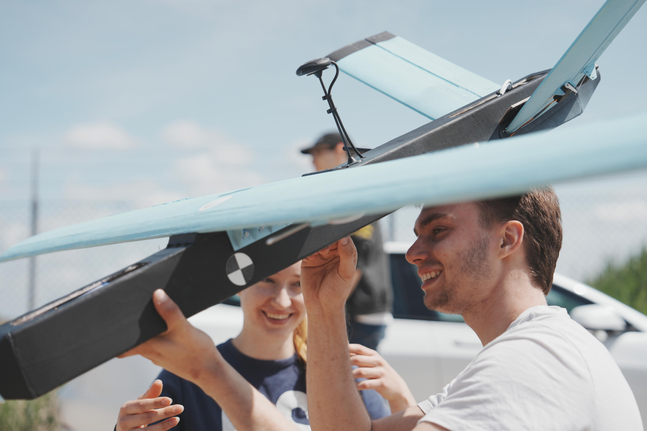
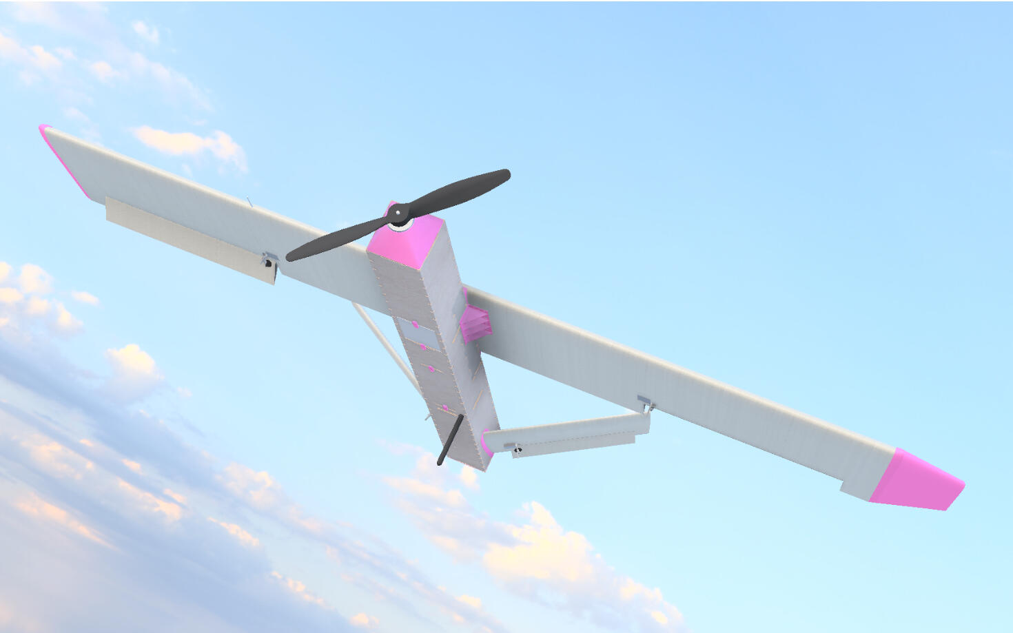
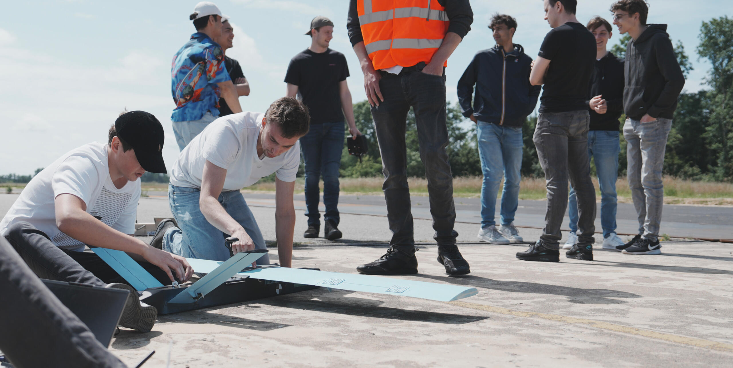
Unmanned Aerial Vehicle
Autonomous flight with speeds up to 34.2 m/s
Design
The UAV was developed with a focus on low weight and high aerodynamic performance. It weighs 3.02 kg fully equipped and can sustain a top speed of 34.2 m/s in level flight. Design for Manufacturing (DFM) and Design for Assembly (DFA) were applied from the start to reduce build time and minimize component complexity. Production cost targets were also integrated into material selection and part geometry.
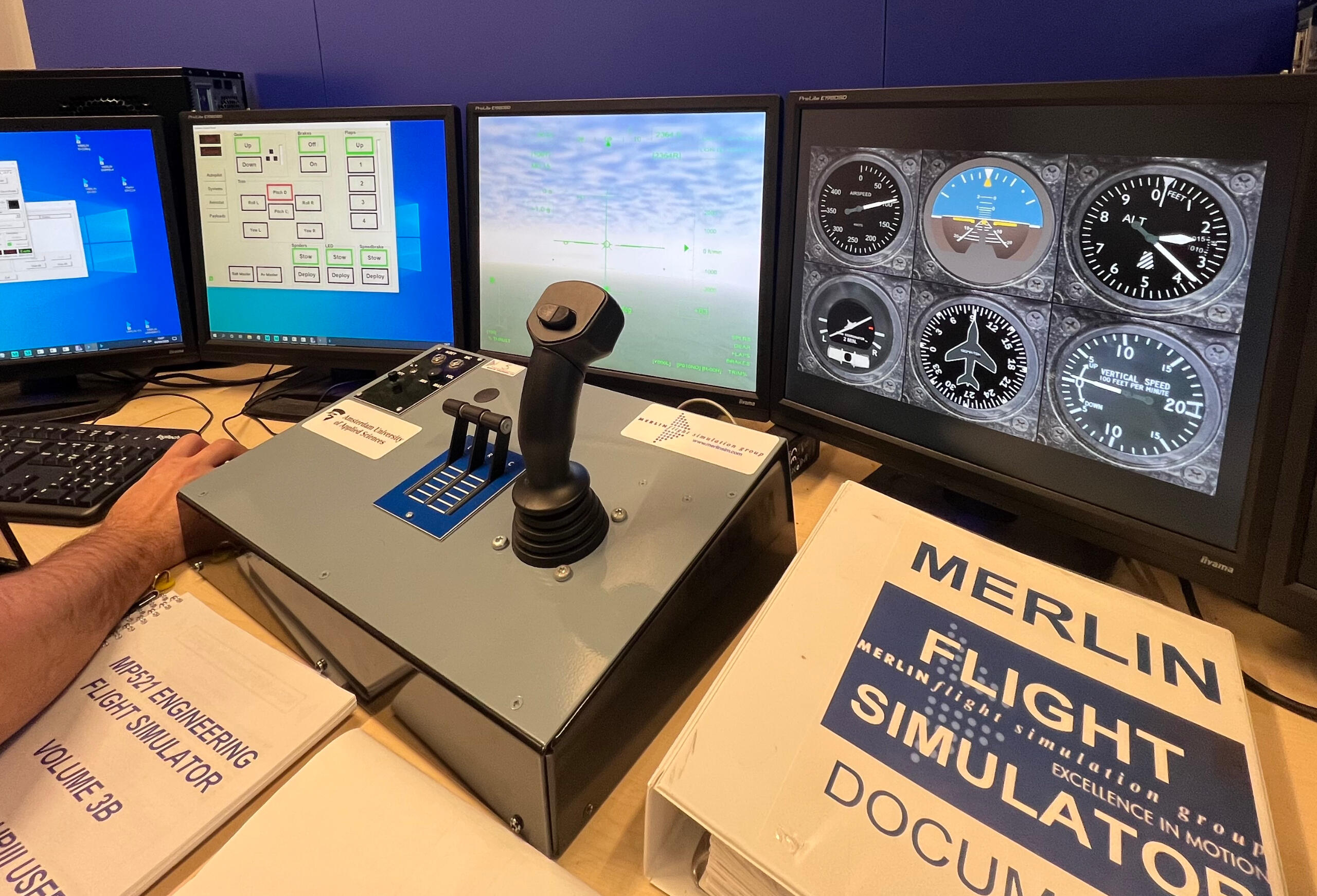
Validation
Flight characteristics were validated in the Merlin Simulator before any physical components were produced. This included evaluating static and dynamic stability, control surface authority, and propulsion efficiency. The simulations confirmed that the UAV maintained a positive static margin of 7% and achieved stable flight in crosswinds of up to 8 m/s.
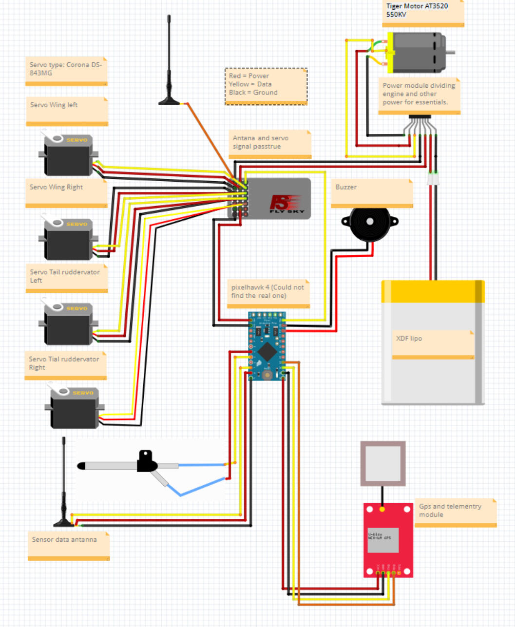
Wiring diagram
Electronics form the backbone of the UAV’s autonomous capabilities. The wiring architecture integrates propulsion control, stabilization algorithms, GPS navigation, telemetry, and onboard data logging. A detailed wiring diagram was produced to ensure correct routing and minimize interference, reducing troubleshooting time during assembly by 40%.
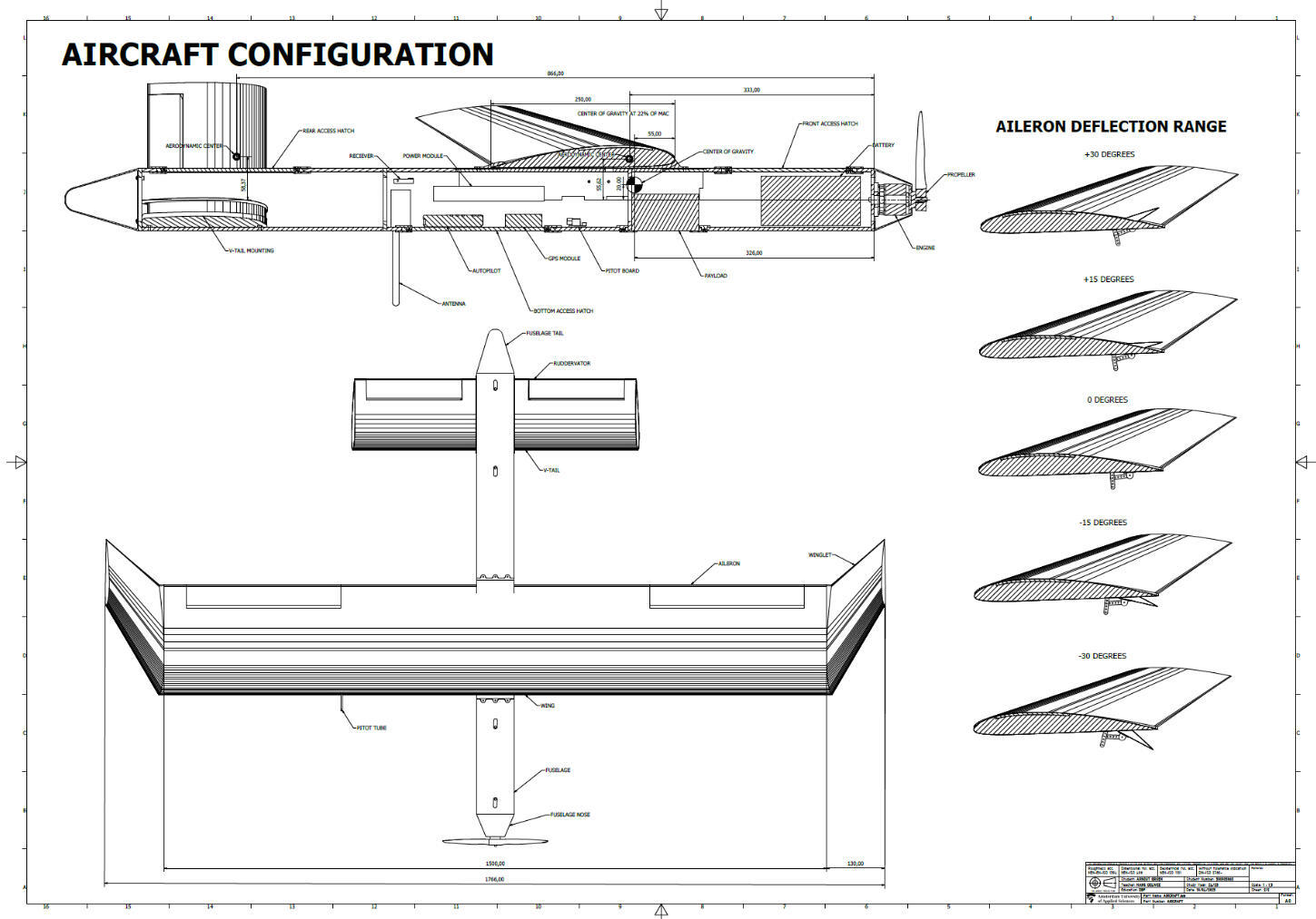
Aircraft schematics
Production drawings were created using GD&T to communicate critical tolerances and alignment requirements. These schematics provided precise reference points for both in-house manufacturing and external suppliers, ensuring all structural and aerodynamic components matched the CAD model within ±0.2 mm.
3D printing
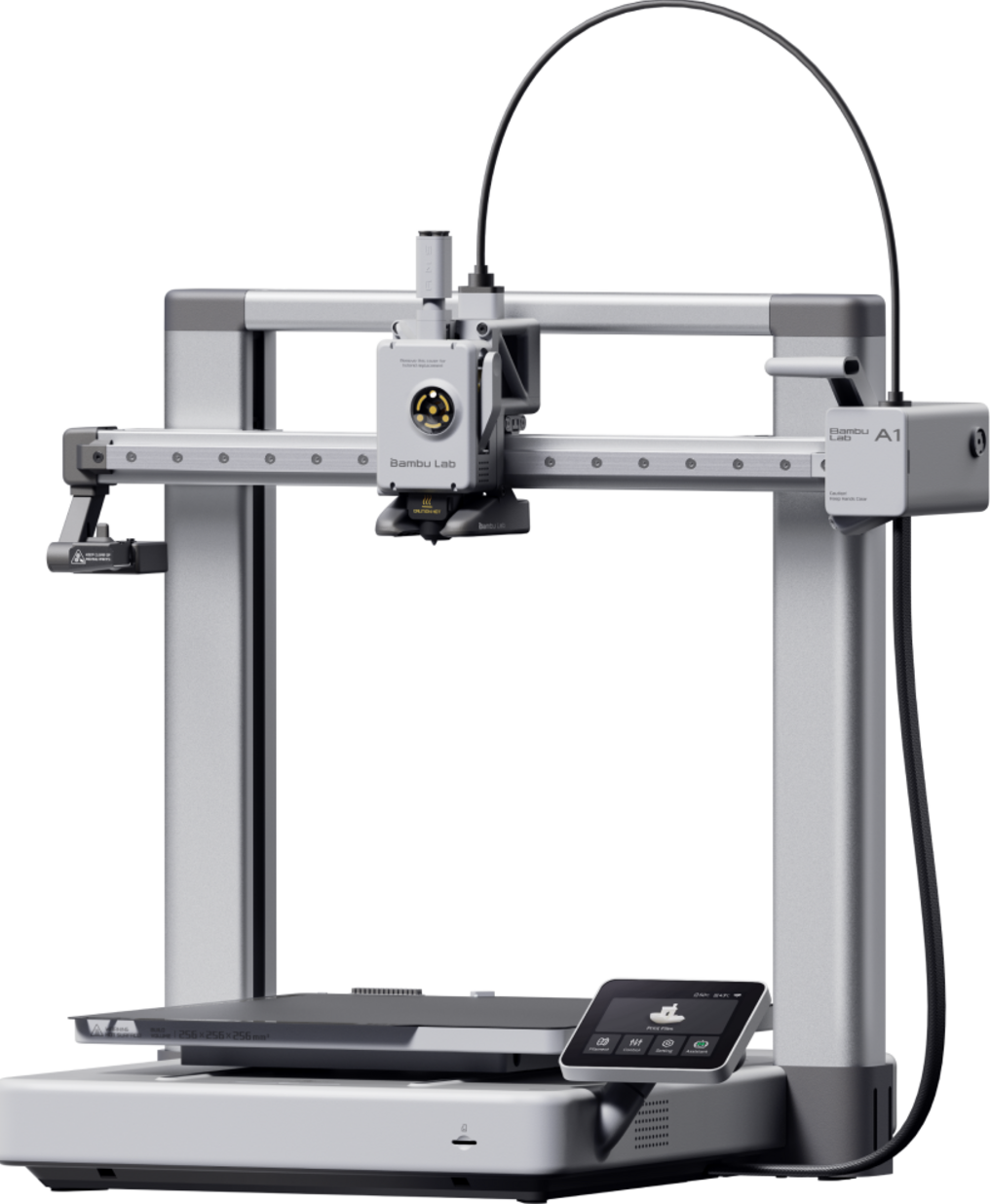
Additive manufacturing was used for components where rapid iteration and cost savings were essential. Using a Bambulab A1 printer, I produced V-tail alignment brackets, wing attachment points, and aerodynamic fairings. These parts were printed with tolerances within ±0.15 mm and achieved production in under 4 hours, reducing outsourcing costs by 65%.
Composite materials
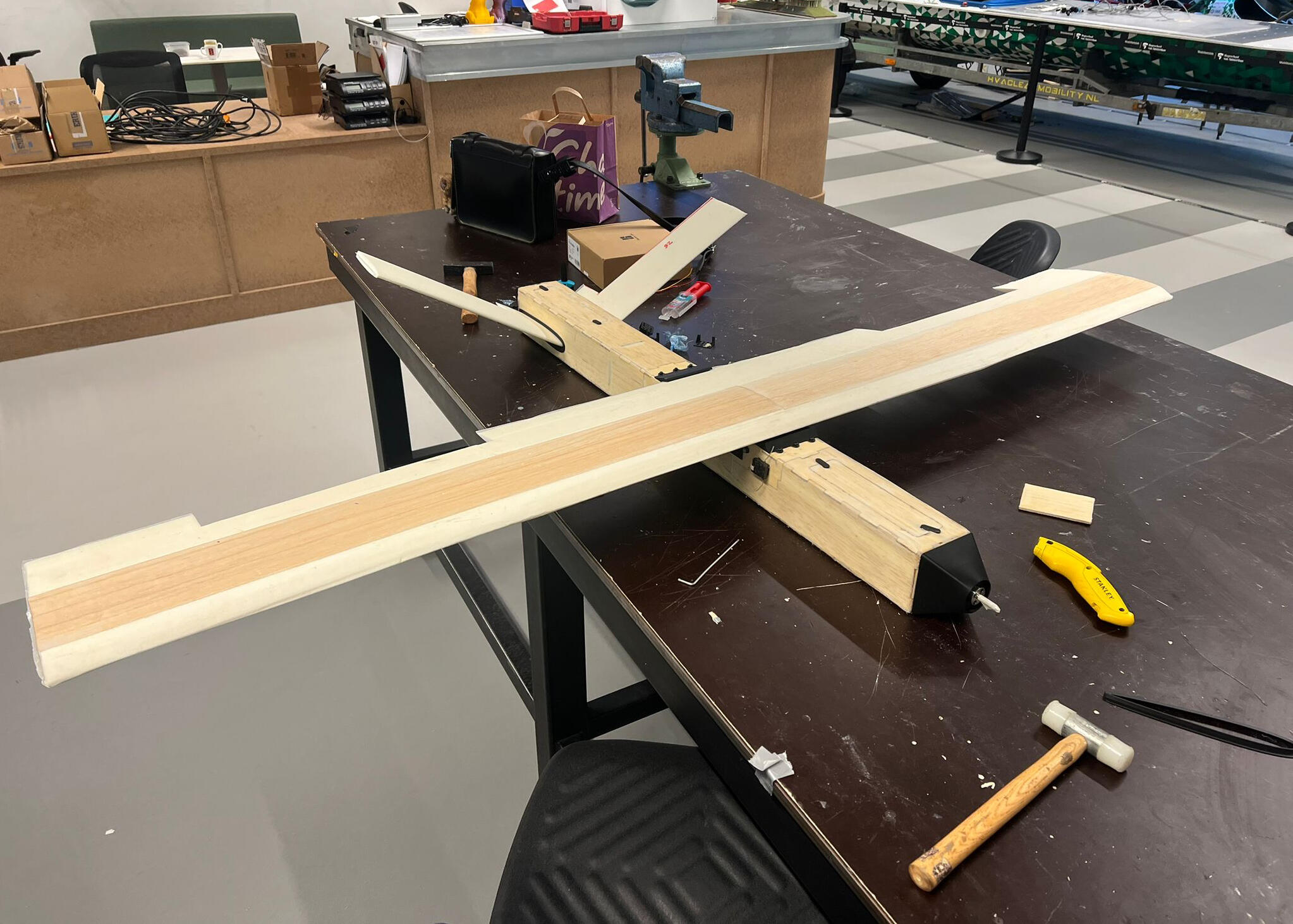
The fuselage was constructed from 4 mm balsa wood reinforced with 80 gsm glass fibre, creating a lightweight yet rigid structure capable of withstanding flight loads of up to 120 N. The main wing and V-tail were shaped from XPS foam, also glass fibre reinforced, resulting in a structure with a weight-to-strength ratio comparable to commercially available UAV kits.
Assembly
The aircraft consisted of over 100 individual parts. DFA principles allowed for streamlined assembly, with key structural components designed for self-aligning fits. Total assembly time was reduced to 6 hours while ensuring repeatable, high-quality builds.
Mission flight
The mission objective was to autonomously deliver a 200 g payload. After a manual hand launch, the UAV achieved its target cruise speed, navigated to the drop zone, and deployed the package with a positional error of less than 1.2 meters. The return flight and autonomous landing were completed without incident, with the airframe sustaining no damages.
Tools used in this project:


Skills applied in this project:
FEM analysis
Design for Manufacturing (DFM)
Design for Assembly (DFA)
Geometric Dimensioning and Tolerancing (GD&T)
Tolerance analysis
Parametric design
composite fabrication
Aerodynamic design
Rapid prototyping
Circuit layout
systems intergration
3D printing
fully parametric cd wall display
Designed to display my love for music

so many cd’s…
With the rise of streaming and digital licensing, owning media has shifted away from permanence. Today, a physical copy is often the only way to ensure access to music you truly own. For me, collecting CDs became more than nostalgia it became a personal archive of the music that shaped who I am. By mid-2024, my collection had grown to over 50 discs, and I decided to put part of it on display.
From spreadsheet
to model
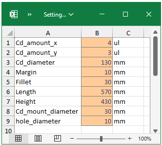
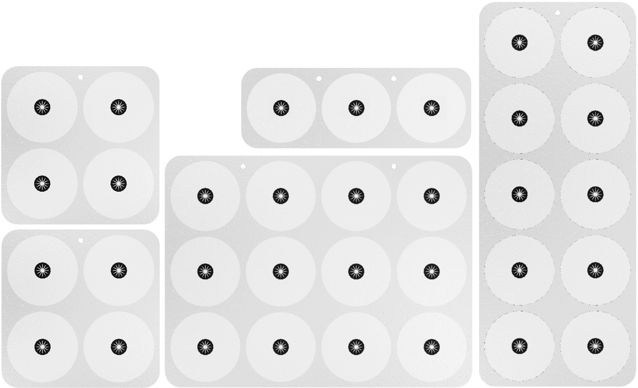
Since I wasn’t sure how many CDs I wanted to feature, I designed a fully parametric model using an Excel sheet linked to Autodesk Inventor. This setup let me change the number of rows, columns, spacing, and margins with a few inputs, and the model would update instantly. The same sheet also stored standard CD and hub dimensions to ensure consistency in every version of the layout.
Tailored for the wall
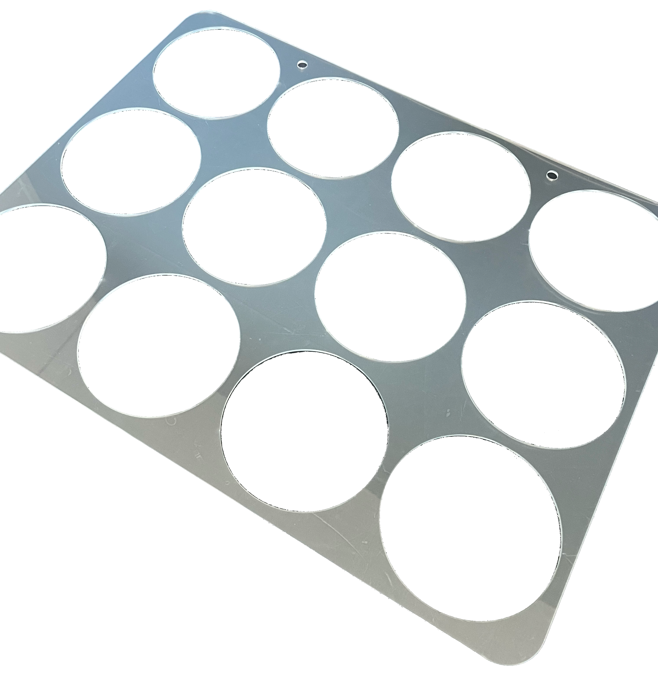
Once the design was parametric, I explored different layout sizes directly in Inventor. This gave me a precise understanding of how the final product would sit on my wall. I chose 4 mm clear PMMA for its transparency and ease of processing. The display was structured around three parts: a base panel, a transparent top layer, and a set of CD hubs designed to hold discs snugly in place.
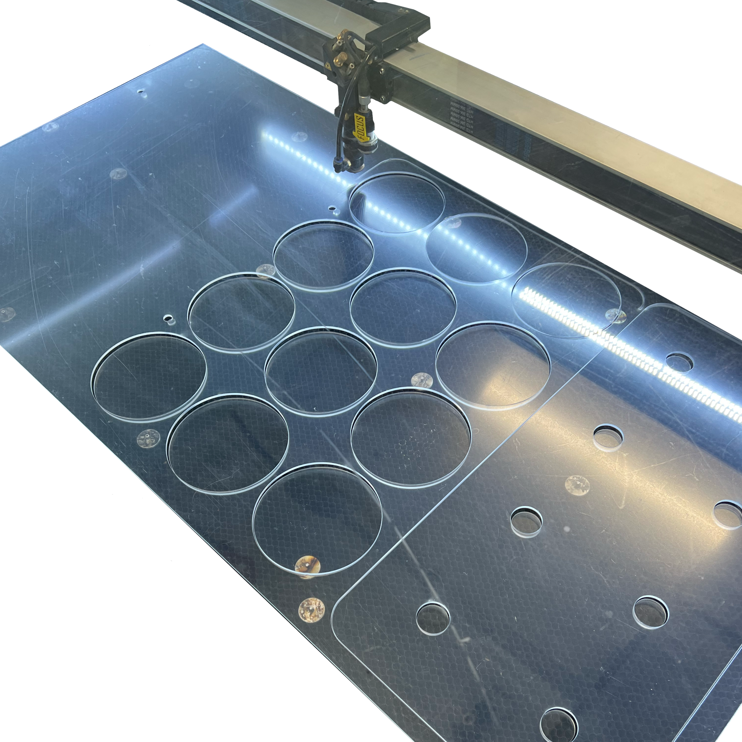
Preparing production
To manufacture the parts, I exported the cut outlines to DXF format and brought them into AutoCAD. I arranged cut priority using color layers, ensuring the laser cutter would process small internal holes first to avoid any sheet sagging. This step helped me avoid common issues like burn marks or defocused cuts, especially with delicate features like hub slots.
Building the display
Once the laser-cutting was done, I used capillary action glue designed for acrylics. This glue chemically softens the plastic surfaces, which then rebond under UV curing. This created a nearly invisible join between the top and bottom panels. I then installed the hubs using a press-fit method refined through a few quick prototyping iterations.
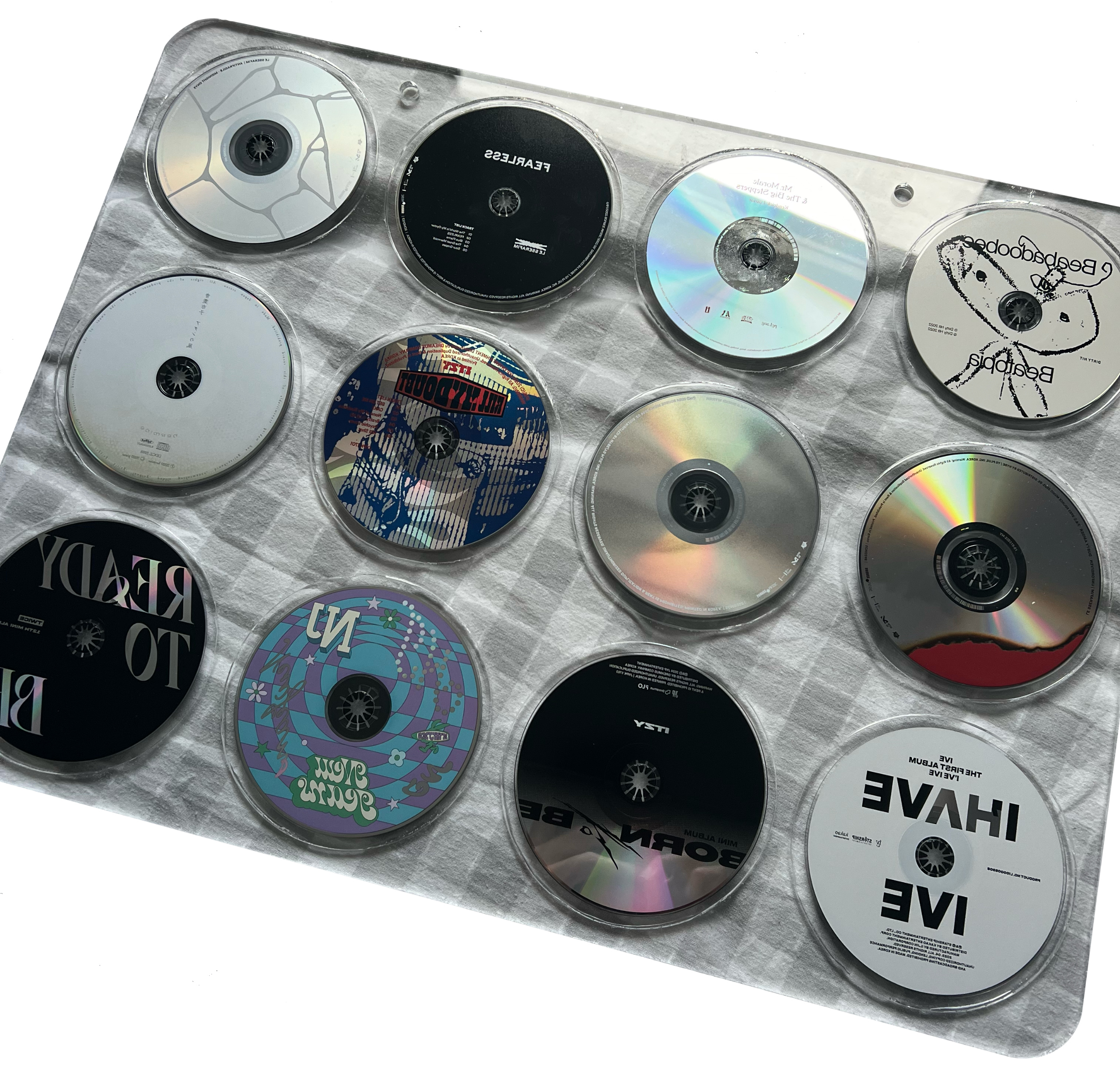
The finished product
The final result is a clean, modular CD wall display that holds up to 12 discs per unit. Its transparent appearance makes the music the visual focus, while the frame fades into the background. With the parametric control, I can easily replicate or resize the design in under 10 minutes and send it directly to a laser cutter. What started as a personal display now works as a flexible system for growing collections.
Tools used in this project:


Skills applied in this project:
Design for Manufacturing (DFM)
Design for Assembly (DFA)
Tolerance analysis
Rapid prototyping
Parametric design
Laser cutting
Material science


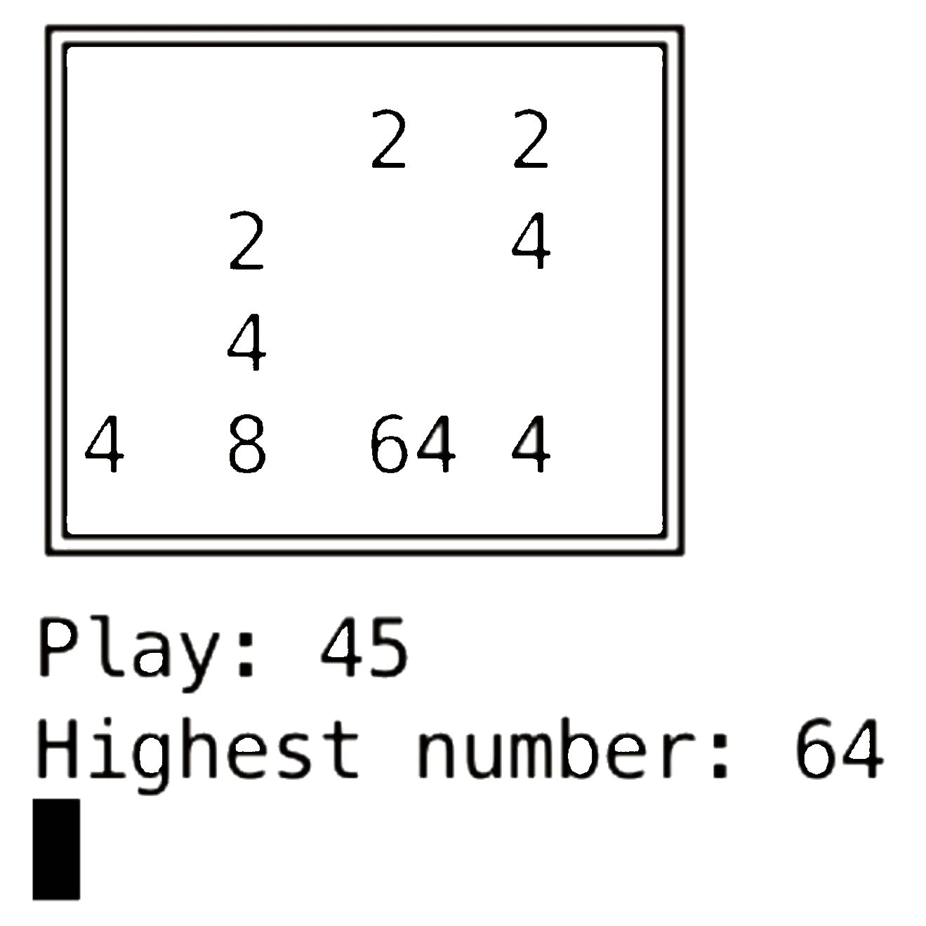
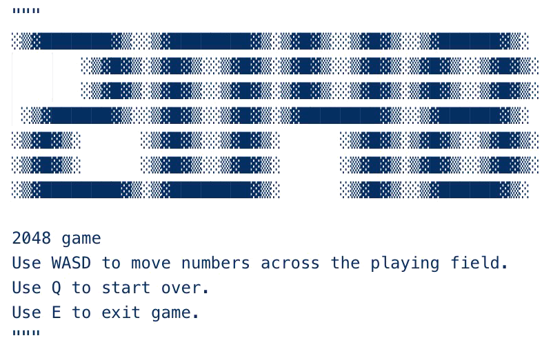
ASCII
2048 game
Python terminal implementation with endless mode and custom UI
Design
This version of 2048 was built entirely in Python to run directly in the terminal. The game uses a 4×4 grid and supports responsive WASD controls for movement, with Q to restart and E to exit. Players can toggle single or double-line borders, bold text, and move counters. Endless mode is available for players who want to continue past the 2048 tile.
Game logic
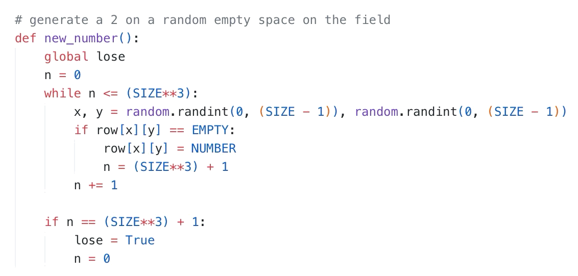
The movement system follows the original 2048 rules. After each move, all tiles slide in the chosen direction, merge with matching neighbors, and spawn a new tile in a random empty cell. Vertical moves reuse the same logic as horizontal moves by rotating the board in memory, reducing duplicate code. Win and loss detection runs automatically, and the game keeps track of the highest tile and total moves made.
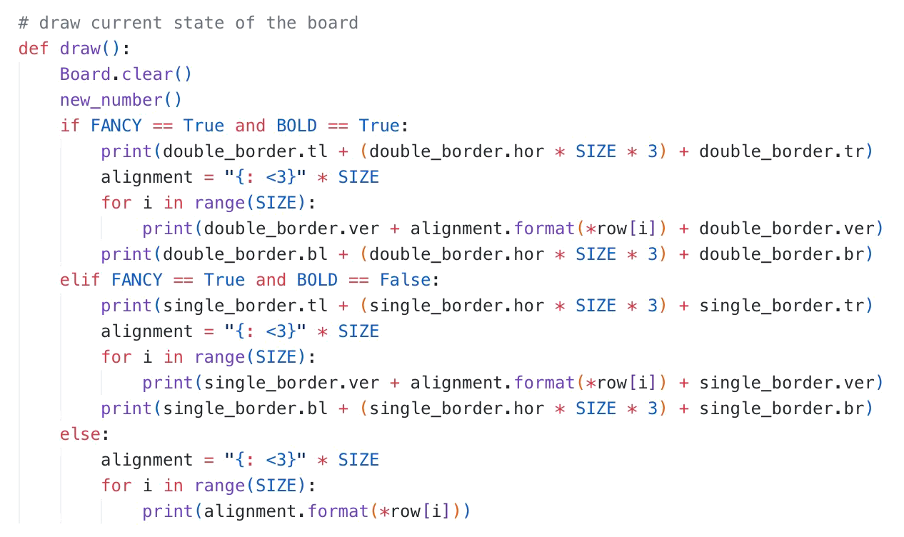
Board rendering
The board is rendered in ASCII characters for maximum compatibility. The layout aligns each cell neatly within a fixed-width format so numbers remain readable even at higher values. The border style can be switched between single and double-line characters without changing the game logic, thanks to a separate Border class that holds all rendering symbols.
Structure
The program is organized into a Board class for generating, displaying, and updating the game state, a Move class for handling movement and merging, and helper functions for spawning tiles and checking win/loss conditions. The main() function runs the game loop, reads player inputs, applies changes to the board, and instantly redraws the updated state.
Performance
All operations are lightweight enough to run instantly in a terminal environment without noticeable delay. The rotation-based movement system avoids writing separate logic for each direction, which keeps the code compact and easy to maintain. Testing confirmed that even with move counters and visual enhancements enabled, the game responds immediately to player input.
Tools used in this project:

Skills applied in this project:
Python programming
Algorithm design
Class-based architecture
debugging & testing
Send me a message!
Thank you for your message!
I’ll respond as fast as I can…
Hi, I am
Arnout Groen
a mechanical engineering student at the Amsterdam University of Applied Sciences with a passion for building smart, manufacturable systems that connect mechanical design, electronics, and software.My work blends technical precision with creative problem-solving, from designing autonomous drones with integrated sensor suites to engineering high-fidelity speaker systems optimized for performance and cost. I care deeply about DFM/DFA, tolerance control, and cross-disciplinary collaboration, and I aim to build solutions that work reliably in the real world.When I’m not prototyping or modeling in CAD, I enjoy exploring data-driven tools like Python and Power BI to make better design decisions. I’m currently open to internship or project opportunities where I can contribute to ambitious teams pushing hardware innovation.

Built to Explore
My story, from playful builds to professional design.
Start
2008 - Discovery
It all began with a shovel. As a kid, I couldn’t resist it I spent hours helping my dad with backyard projects, moving sand into the sandbox, or just watching construction sites in awe. I was hooked on building things before I even knew what “engineering” meant.

2010 - Building worlds
Then came LEGO. First the basic bricks, then LEGO Technic, and suddenly I wasn’t just building I was engineering. I created entire cities, documented the construction in stop-motion films, and started to understand how things worked beneath the surface.
2014 - First automation
For my 9th birthday, I received LEGO Mindstorms. That microcontroller opened a new universe. I built tanks, vending machines, security systems even classroom demos. It was the moment I realized that mechanics and programming could come together to make things move, think, and interact.

2018 - Expanding curiosity
In secondary school, subjects like physics, chemistry, and math gave shape to my curiosity. I started applying logic in new ways building cardboard planes, wiring circuits, and even using Minecraft Redstone to simulate real-life contraptions. It wasn’t just play anymore it was applied problem-solving.

2025 - Becoming an engineer
After high school, I enrolled in Mechanical Engineering at the Amsterdam University of Applied Sciences. Since then, I’ve worked on UAVs, acoustics, geolocation analysis, and more. I interned at a company building systems for dredging vessels and now work at an engineering firm analyzing market data for new product opportunities.
Today
Experience
Turning ideas into working solutions
Today

Machined4You
Project Engineer
mar 2025 - present - Amsterdam, The Netherlands
Leading weekly design reviews and coordinating cross-functional feedback, reducing project delays by∼30%
Designing and reviewing mechanical assemblies for DFM, tolerance stack-up, and production alignment
Analyzing market trends to support product strategy and investor materials

Vosta LMG
Mechanical Engineering Intern
aug 2024 - feb 2025 - Hoofddorp, The Netherlands
Researched & developed an electric ship anchoring system increasing energy efficiency by∼50% & reducing emissions
Collaborated with 2 external suppliers and 3 internal departments to integrate off-the-shelf & custom components
Wrote a comprehensive 40-page report detailing the R&D process to guide future electrification efforts
2017
Education
Learning the principles that shape my work
Today

Amsterdam University of Applied Sciences
Bachelor of mechanical engineering - (Average 7.5/10)
sep 2022 - aug 2026 - Amsterdam, The Netherlands

Keizer Karel College
Secondary education (HAVO) - Major: Nature and Technology
sep 2017 - aug 2022 - Amstelveen, The Netherlands
2017
Skills
My core strengths at work
Design & CAD
Engineering Methods
Prototyping & Manufacturing
Autodesk Inventor (incl. Nastran)
AutoCAD
Fusion 360
Python
Excel (advanced modeling)
Power BI
GD&T
DFM / DFA
Tolerance Analysis
FMEA
STPA
Root Cause Analysis (RCA)
3D printing
Laser cutting
Lamination
CNC
CAM